
I am trying to retrofit an APS+ to my car that does not have any park assist.
I am done installing the rear sensors, control unit, rear buzzer, and I have wired all cables to the front passenger side. I have made my own cables from a donor car and wired them according to ELSA wiring diagrams.
At this point and since I have wired power, earth, and CAN-BUS to the controller, I expected that the new park assist module would be detected by the car.
I went on coding with VCDS: I added the module Address 10: Park/Steer Assist from the installation list to the CAN gateway module.
However, address 10 is not accessible and I get the following error in the CAN Gateway module:
Address 19: CAN Gateway Labels: 8T0-907-468.clb
Control Module Part Number: 8T0 907 468 H HW: 8T0 907 468 H
Component and/or Version: GW-BEM 5CAN H06 0094
Software Coding: 000303
Work Shop Code: WSC 06325 000 00000
1 Fault Found:
01327 - Control Module for Parking Aid (J446)
004 -- No Signal/Communication
Freeze Frame:
Fault Status: 01100100
Fault Priority: 2
Fault Frequency: 1
It seems that there is either something wrong with the way CAN cables have been wired or the parking module (J791) is faulty (bought it used on ebay). Furthermore I am not sure why the error refers to J446 instead of J791 that is the standard Parking Aid module in a5.
I have tried 2 different wiring methods for the CAN cables.
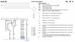
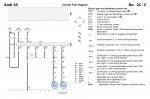
1. According the the ELSA wiring diagrams (see attached pictures) the CAN wires from J791 follow the exact same path (main wiring harness connections to T17f connector in A pillar and finally to T46s CAN separating connector in dash panel) as the CAN wires from the electric park and handbrake control unit (J540). Thus, I decided to connect the CAN wires from J791 to the CAN wires from J540. This did not work. I even got and error when trying to access the handbrake module J540 and decided not to go this way.
2. I did the wiring suggested by Kufatec in their guide for retrofitting APS+ that I found in another a5oc thread(see attached pdf and picture). According to them the CAN wires should go directly to T46s CAN separating connector in dash panel pin 6 High and 6 Low.
This is where I am at the moment. The park aasist module is not recognised.
Any suggestions to what may be wrong?
1. Wiring
2. Coding
3. Faulty control unit (J791)
I am done installing the rear sensors, control unit, rear buzzer, and I have wired all cables to the front passenger side. I have made my own cables from a donor car and wired them according to ELSA wiring diagrams.
At this point and since I have wired power, earth, and CAN-BUS to the controller, I expected that the new park assist module would be detected by the car.
I went on coding with VCDS: I added the module Address 10: Park/Steer Assist from the installation list to the CAN gateway module.
However, address 10 is not accessible and I get the following error in the CAN Gateway module:
Address 19: CAN Gateway Labels: 8T0-907-468.clb
Control Module Part Number: 8T0 907 468 H HW: 8T0 907 468 H
Component and/or Version: GW-BEM 5CAN H06 0094
Software Coding: 000303
Work Shop Code: WSC 06325 000 00000
1 Fault Found:
01327 - Control Module for Parking Aid (J446)
004 -- No Signal/Communication
Freeze Frame:
Fault Status: 01100100
Fault Priority: 2
Fault Frequency: 1
It seems that there is either something wrong with the way CAN cables have been wired or the parking module (J791) is faulty (bought it used on ebay). Furthermore I am not sure why the error refers to J446 instead of J791 that is the standard Parking Aid module in a5.
I have tried 2 different wiring methods for the CAN cables.
1. According the the ELSA wiring diagrams (see attached pictures) the CAN wires from J791 follow the exact same path (main wiring harness connections to T17f connector in A pillar and finally to T46s CAN separating connector in dash panel) as the CAN wires from the electric park and handbrake control unit (J540). Thus, I decided to connect the CAN wires from J791 to the CAN wires from J540. This did not work. I even got and error when trying to access the handbrake module J540 and decided not to go this way.
2. I did the wiring suggested by Kufatec in their guide for retrofitting APS+ that I found in another a5oc thread(see attached pdf and picture). According to them the CAN wires should go directly to T46s CAN separating connector in dash panel pin 6 High and 6 Low.
This is where I am at the moment. The park aasist module is not recognised.
Any suggestions to what may be wrong?
1. Wiring
2. Coding
3. Faulty control unit (J791)